Introduction
In developing custom impellers for high-performance pumps, compressors, or turbines, project teams often encounter a frustrating “trilemma” where a G2.5 high dynamic balance grade results in exorbitant costs and lead times of 12+ weeks, while a low-cost supplier results in a product with excessive vibration and lifespan issues, causing costly field failures and project delays. The underlying problem is that conventional impeller production is heavily dependent on human expertise and a “trial and error” approach. Unpredictable chatter vibrations, deformation of thin walls, and residual stresses during machining result in a high percentage of scraps, while subsequent correction and balancing require enormous time and money. As a result, cost, quality, and lead time appear to be mutually exclusive variables.
In this article, we will unveil how to break this deadlock using a deterministic data-driven approach for 5-axis impeller machining. In fact, we will walk you through how to analyze the process of moving from “experience-dependent” to “predictive control.” This will allow you to reduce your costs by 20% and still meet your G2.5 balance requirements for your first piece, with predictable delivery. But how do you start? Well, first of all, you need to redefine what you really need to do: it is not about cutting metals; it is about mastering material science and dynamics.
Is Your Impeller Machining Problem Really About Cutting Metal, or Controlling Physics?
This section will redefine the problem of machining the impeller. It will be suggested that the key to successful machining is to control the complex physics of the machining process in a virtual environment.
1. The True Adversaries: Dynamics, Geometry, and Material
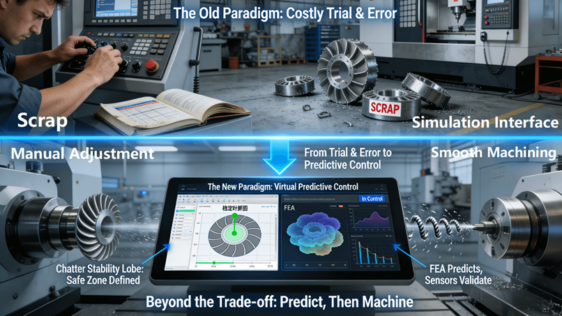
Imagine the machining problem is a closed titanium impeller. What is the problem? Is it the geometry of the part? Not really. Is it the material? Not the material itself but the physics of the machining process. Extremely thin blades have low dynamic stiffness and therefore are very prone to chatter. Flow channels inside the part can cause tool accessibility and rigidity issues. Inconel is very prone to work-hardening. If the tool parameters are not correct, the machined surface will be very difficult to machine further. In the past, these problems have been solved through trial and error on the machine. This is a costly and time-consuming approach. It is a gamble. The ASM International Handbook is one source that describes the difficult mechanical and thermal properties of these alloys.
2. The Predictive Engineering Solution: Simulating Before Machining
The modern solution flips the script entirely. It starts with the creation of a highly accurate digital twin of the machining process. Finite Element Analysis (FEA) is employed in the modeling of the deformation of the workpiece during the machining process. Chatter stability lobe simulation software is then employed in the prediction of the spindle speed and the depth of cut that would cause unstable vibrations for the specific tool and part geometry in question. This virtual prototyping enables the engineer to solve problems in the virtual world instead of the physical world. To gain an in-depth and thorough understanding of the methodology involved in the integration of material science, simulation, and advanced process systems, this in-depth technical guide on 5-axis impeller machining presents an exhaustive analysis.
3. From Guesswork to Calculated Risk
The approach taken in this prediction method fundamentally changes the economics because the cost of physical scrap or rework is replaced by the very low cost of calculation or simulation. It enables a design for a machining operation that is inherently stable and predictable, which fundamentally changes the cost and risk profile for making complex titanium or nickel alloy impellers. The transition from a reactive approach to a proactive approach is at the heart of modern precision engineering, which represents a quantum improvement in both cost control and quality assurance.
How Can “Cost Drivers” Be Transformed from Guesses into Calculated Variables?
This section outlines a quantitative approach for analyzing and controlling impeller manufacturing costs, which shows how data-driven strategies can be used to directly address the greatest cost drivers.
1. Deconstructing the Total Cost Model for Strategic Optimization
In a data-driven paradigm, total cost is decomposed into controllable, optimizable variables instead of being treated as a monolithic black box. Three main areas are identified: the strategy around raw material, or focusing on drastically minimizing the expensive “buy-to-fly” ratio by optimizing the near-net-shape blank; machining cycle time, often the most dominant cost factor and dependent upon toolpath efficiency and non-cutting time; and the often-overlooked, yet inherently minimized, cost of quality assurance and rework, which is a byproduct of a predictable, stable process.
2. Targeted Optimization Through Intelligent, Adaptive Machining
One of the best examples of the application of data-driven cost control is the concept of adaptive or variable feed rate machining. In the CAM system, the tool path is intelligently analyzed in real-time to identify zones of heavy tool engagement, such as full-width cuts, and zones of low part rigidity, such as thin blades. In these zones, the machine will be slowed down to prevent chatter and deflection, while the feed rate is optimized to increase the metal removal rates in zones of rigid parts. This not only optimizes the machine time by as much as 20-25%, but it is a direct and efficient approach to controlling the largest cost component without sacrificing the result.
3. Elimination of Hidden Costs Associated with Process Uncertainty
Besides the direct and quantified machining time, having a predictable and data, validated process enables one to systematically get rid of various hidden costs that are, to some extent, inevitable in a more traditional manufacturing approach. Direct cost elements related to emergency tooling, air freighting of replacement materials or parts, and most importantly, unplanned downtime of the production line due to late or non, conforming components or materials are some of these hidden costs. Turning these key cost aspects from speculations into actuals will reduce the overall project financial risks and help lead to a better overall supply chain optimization solution.
What Defines “Quality” for an Impeller? It’s More Than a Pass/Fail on a Drawing.
In this section, we redefine what we mean by quality for an impeller as a set of quantified variables critical to performance.
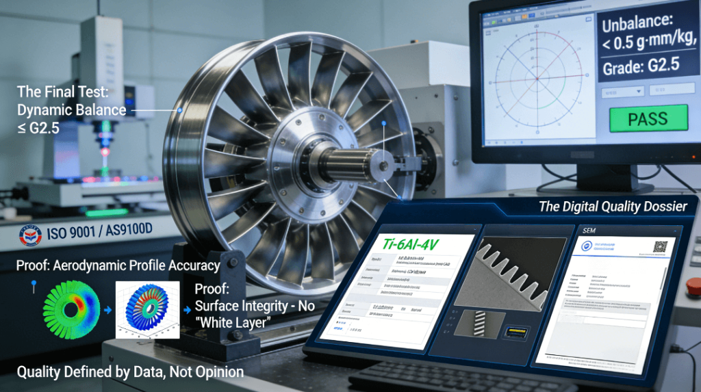
1. The Holy Trinity of Quantifiable Impeller Performance Metrics
It is true that the real quality definition for the impeller is based on three measurable and highly correlated aspects: the accuracy of the aerodynamic profile within ±0.05mm on the pressure and suction surfaces; the integrity of the surfaces, which are free from internal damage such as the “white layer” fatigue crack initiation site; and the Dynamic Balance Grade (G2.5 and above), the ultimate test for the symmetrical mass distribution of the impeller. All this is done through the latest technology in metrology tools such as optical 3D scanners and microscopic analysis.
2. The Strategic Shift from Dimensional Conformance to Functional Performance
Clearly, the fundamental shift in the evolution of quality thinking has been the move from “the part matches the drawing” to “the part will perform reliably for its intended service life.” A supplier who only focuses on “passing” a part based on dimensional tolerances measured with a caliper may deliver a part that meets all specifications on a 2D drawing but fails prematurely in service because of a poor surface finish, residual stress, or imbalance. Hence, the clear translation of this clearly articulated quality metric into a deterministic output of batch-to-batch delivery represents the fundamental value proposition of a top-tier 5-axis CNC machining services provider.
3. Data as the Irrefutable, Objective Proof of Quality
All of the above performance metrics produce a wealth of objective data. The 3D scan color map deviation report, the metallurgical micrograph, and the formal balance certificate all add up to a thorough digital quality file. This file acts as irrefutable proof of performance readiness for the customer. It is a permanent record for purposes of traceability. This method shifts the focus from the subjective sample-based quality assessment model to a thorough data-based quality verification model. This is the heart and soul of quality assurance in production for high-stakes industries.
Which Process Strategies Actually Compress “Lead Time” Without Gambling on Quality?
This section examines the effective strategies for compressing impeller lead time. It is submitted that the only way to truly compress lead time is through the optimization of the entire production process and the elimination of non-value-added time through parallel execution and technology, and not through the sacrifice of quality and process rigor.
1. Parallel Process Engineering to Overcome Sequential Bottlenecks
The linear process of design, CAM programming, fixture fabrication, machining, and inspection is another fundamental lead time killer. Concurrent or parallel engineering reduces this lead time by overlapping these non-dependent tasks in the critical path of the project timeline. For example, while machining the first part, CAM programming of the finishing operation may be in progress at the same time. Concurrently, whereas inspection of the first part is in progress on the CMM, fixtures for subsequent parts may be in fabrication.
2. Leveraging Technology Enablers: Quick Change Systems and In Process Metrology
Hardware and software technology are important lead time compressors. Quick change systems can reduce part changeover and setup times from hours to minutes, significantly increasing the utilization rate of the machine tools. On-machine probing and scanning can be used to verify critical features after each machining process. If any deviation is found, the system can be programmed to apply a compensating action in the subsequent machining process, thereby avoiding the long queue time for a CMM inspection and subsequent re-fixturing and correction. This is a direct and quality-enhancing method for how to optimize impeller machining lead times.
3. Building Systemic Reliability for Predictable, Shorter Schedules
While a consistently short lead time is commercially irrelevant if it is not reliable or consistent, this is precisely what a well-designed and well-implemented system of process control can deliver. Standards like IATF 16949 require the implementation of Advanced Product Quality Planning (APQP) and the Production Part Approval Process (PPAP), which require detailed documentation, validation, and locking-down of processes prior to the start of production. This ensures that the optimized parameters and sequence of operations that were successful for the prototype are precisely and repeatedly applied for production. It makes the quoted impeller lead time a reliable and binding commitment, rather than a hope based upon past experience.
The Supplier Audit: 3 Questions to Uncover Real 5-Axis Impeller Expertise
In this final section, we will provide a checklist of questions designed to determine whether a supplier has real expertise in 5-axis impeller design and manufacturing, as opposed to simply possessing capable machines and skilled operators.
1. Seeking Conclusive Evidence of Predictive Capabilities and Correlation
Don’t fall for marketing promises or vendor-supplied machine lists. Ask your prospective vendor: “Can we be provided with the machining simulation video showing tool paths, material removal, and cutting forces, as well as the dynamic balance test report and 3D scanning report for a past project of comparable size and complexity?” The direct relationship between a clean and stable simulation and the production of a first-article part that meets G2.5 balance requirements with minimal dimensional deviation is the ultimate proof of predictive engineering competence.
2. Probing for Adaptive, Data-Infused Systems and Real-Time Resilience
Challenge their depth of operation and ability to deal with process abnormalities by asking: “How does your system react to unusual tool wear, as detected by in-process sensors in a long, narrow flow channel? What data are used to make this determination, and what corrective action takes place?” Be listening for references to closed-loop controls, adaptive feed rate changes, and tool life monitoring, all of which are used to drive a live digital model of the process. A data-driven, self-correcting process is a hallmark of advanced manufacturing, as might be envisioned in models such as those offered by the National Institute of Standards and Technology (NIST).
3. Evaluating Institutional Knowledge and Strategic Partnership Value
Evaluate their long-term value as a true engineering partner, as opposed to a job shop. Ask: “Do you have a searchable database of successful machining parameters (feeds, speeds, tools) for various blade configurations and materials? Additionally, can your DFM analysis utilize similar past cases to quantitatively validate its recommendations?” A supplier that systemizes, leverages, and is willing to utilize past project data is one that has a culture of continuous improvement and is a true partner to your engineering organization. This will give you invaluable CNC machining tips and is in line with the vision of interconnected, smart manufacturing where knowledge is a shared resource.
Conclusion
In the world of high-end turbomachinery, the effectiveness of 5-axis impeller machining is now no longer dependent upon the accuracy of the machine tool or the skill of the operator in isolation. It is now dependent upon the implementation of a deterministic manufacturing system, which combines the disciplines of predictive engineering, adaptive real-time control, and closed-loop quality data verification in a seamless manner. It is now possible for the engineering and procurement community to adopt this data-centric philosophy and turn what has historically been a zero-sum constraint on project outcomes into a scientific discipline that can now be modeled and understood in a synergistic manner.
FAQs
Q1: What is the reasonable lead time and minimum order quantity for a precision 5, axis impeller?
A: We can handle one, off prototype products with zero MOQ. A lead, time for a medium, complexity aluminium impeller is 3, 4 weeks from the date of approval of the drawings. Lead, time for titanium and nickel, based alloys is longer at 5, 7 weeks as these require more time for detailed planning, simulation analysis, and stress relieving.
Q2: What level of dynamic balancing and surface finish are achievable on a consistent basis?
A: We can achieve a consistent level of dynamic balancing up to G2.5 for pumps and compressors. Turbines and other high-speed machines can achieve up to G1.0. The aerodynamic blade profile accuracy is within ±0.05mm on a consistent basis. Surface finish in the flow channel area is within the range of 0.8 to 1.6 microns on a consistent basis.
Q3: Do you provide Design for Manufacturability feedback before the quoting process?
A: Yes! In fact, it is our pleasure to analyze your CAD file for Design for Manufacturability and provide a detailed report of any design elements that may affect the cost, quality, and manufactur ability of your project. This detailed report will also include suggestions on how the design can be optimized to provide better value and reliability for your product.
Q4: What type of inspection documentation is included with the finished impellers?
A: Each finished impeller is delivered with a digital package that includes a 3D scan color map deviation report, a dimensional inspection report, and a formal dynamic balance test report, as well as material certifications that verify the finished product meets all the required performance and specification criteria.
Q5: What is your approach for machining extremely thin impeller blades so that chatter and distortion can be avoided?
A: We utilize a multi-faceted approach for machining extremely thin impeller blades so that chatter and distortion can be avoided. First, we simulate the machining process by utilizing a “damped tooling approach,” a “proprietary machining sequence,” and a “certified ‘low and stable cutting force‘ parameter package.” By utilizing this approach, we can simulate the machining process in advance so that stability can be ensured when machining actually begins.
Author Bio
The information presented in this article is grounded in the extensive engineering expertise of LS Manufacturing, a company specializing in the machining of high-end impellers and complex contoured mechanical components across industries such as energy production and aerospace. As an ISO 9001, IATF 16949, and AS9100D certified manufacturing partner, they are steadfastly committed to applying deterministic engineering methodologies to resolve the most complex challenges their clients face in the machining of powertrain components. Do you need to set higher standards for your next critical impeller machining project to enhance performance and optimize potential costs? Contact them today to receive the “Summary of 5-Axis Impeller Manufacturability and Potential Performance Enhancement Assessment.”